ALL ABOUT ABS
The anti-lock braking system (ABS) on your vehicle regulates braking at the individual wheels, preventing them from locking up. When wheels lock up, tires slide on wet or slick surfaces, compromising both your ability to stop and your steering control.
By preventing wheel lock up, the ABS maintains wheel traction, allowing your vehicle to stop sooner while you keep control of the wheel.
ABS Control Components
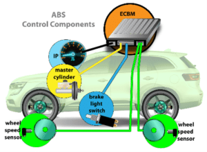 Anti-lock braking systems have both a hydraulic and electrical circuit that work together to provide a safe and controlled braking experience. For an in-depth look at the individual components found in ABS systems and how to diagnose and fix issues, watch our on-demand webinar
Hydraulic System
This system begins at the brake pedal, which is connected to a brake booster and master cylinder. The brake booster provides an assist, increasing the force applied to the master cylinder which then sends pressurized fluid to the ABS pump.
 ABS Module
The ABS module/pump/controller/motor processes information from wheel-speed sensors, to determine when to release braking pressure on a wheel that is about to lock up.
Brake Calipers: Floating and Fixed
Floating calipers are the most popular. They have pistons on only one side and use slide pins to apply pressure to both sides of the brake rotor/disc. Fixed calipers are used in high-performance applications. They have pistons on both sides of the caliper, which apply pressure to the brake rotor/disc.

Wheel Speed Sensors/ABS Sensors
These sensors provide the rotational speed of the wheels to the electronic control unit (ECU). They work in combination with tone, encoder or reluctor rings. There are two types of sensors: active and passive.
Tone/Reluctor/Encoder Rings
These rotate with the wheel, providing the wheel speed sensor with a speed and direction reference. Found in the form of a slotted wheel, a toothed ring or a magnetic strip, they can be part of the wheel bearing or mounted to the axle shaft.
Types of ABS
There are three types of ABS: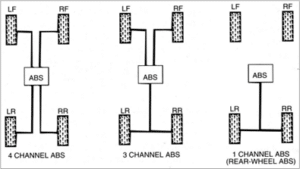
• Four-channel system
• Three-channel system
• One-channel system
Four-Channel ABS
This is the most common and efficient system used in today’s vehicles, and it allows the ABS module to monitor and control each wheel independently. It provides the best braking force and is very effective at keeping the vehicle stable under heavy braking. This setup is also the base of many other integrated traction and stability systems on some vehicles.
Three-Channel ABS
This system is found mostly on pickups. The front wheels are controlled and monitored independently, but the rear wheels are controlled and monitored as a pair. Both rear wheels need to lock up before the system will activate in the rear.
One-Channel ABS
This system is found in older trucks with rear wheel ABS. The front wheels have no ABS control.
One valve and one wheel speed sensor control and monitor both rear wheels as a pair. Both wheels need to lock up before the system activates.
ABS Technologies
Some vehicles expand on a typical anti-lock braking system to include other safety systems, like:
- TCS (traction control system)
- ESC (electronic stability control)
- BAS (brake assist program)
- ESP (electronic stability program)
- Collision avoidance
Symptoms of a Failing ABS
When the anti-lock braking system fails, the following symptoms are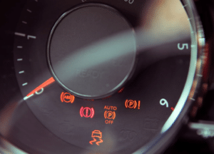 common:
- ABS warning light illuminates
- Traction control, stability control and/or parking brake light may also illuminate
- Fault code is stored
- Brakes shudder at low speeds
- Wheels lock up
Reasons for ABS Failure
There are several reasons why the ABS can fail, including: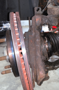
- Sensor out of position or too far away from the tone, reluctor or encoder ring (i.e., when a wheel bearing is worn)
- Physical damage to the wheel speed sensor
- Broken wiring
- Internal short circuits
- Heavy contamination
- Corroded, cracked or swollen ABS ring
- ABS ring blocked, damaged, missing teeth or windows
Diagnosing the Failure
The first step in diagnosing an illuminated ABS light on the instrument cluster is to use a code reader, connected through the vehicle’s OBD2 port, to determine which trouble codes have been stored. The trouble codes will help direct you to the area of the system causing the malfunction.
ABS codes will typically begin with a C, followed by four numbers. Once the faults are determined, the proper diagnostic procedure should be applied to correct the malfunction.
Installation Tips and Tricks
- It is important to first understand the type of sensor being used, prior to
 performing any kind of testing or disassembly.
 - Take care not to damage the ABS sensor, wires or connector when installing any components that are related to the ABS.
- Never handle or hang hub assemblies by the ABS cable.
- Always route and secure wheel speed sensor cables and connectors properly.
- When installing a Gen 1 bearing, always check which side has the encoder ring and install it in the proper orientation using the correct-sized adapter.
- It is also recommended to check any magnetic encoders using a magnetic test card.
For a deeper dive into anti-lock braking systems, along with more tips and best practices from the pros, watch the webinar: All About ABS.
